
Pump performance monitoring and testing - Condition Monitoring - Predictive maintenance
MicroPM Temperature Probes
Standard temperature probes for water utility applications
1. Specification and description
Type no UPM-T6-6-210-M
Measuring range: 0 –45 degree C (also available with calibration extended to 60 °C)
Number of temperature probes: 2 per pump monitor
Number of temperature sensors per temperature probe: 2 (with automated comparison for checking calibration)
Uncertainty of the differential temperature calibration: < 0.5 mK
Long-term stability: typically < 1 mK over 10 years
Uncertainty of absolute temperature calibration: < 50 mK
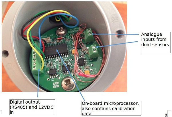
Calibration data: stored in microprocessor in handle
Signal processing electronics: Digitization in probe handle
Power supply: 8 to 12 VDC, less than 10 mA per probe
Output Communications: RS485 half-duplex
Connector: Tajimi R04-R8M connector (8-way)
IP 68 rating (not-submersible) when secured into thermowell with cable attached
Diameter of temperature probe stems: 6 mm
Length of stem: 210 mm standard
Length of probe cable: dependent on site layout, 13 m provided as standard
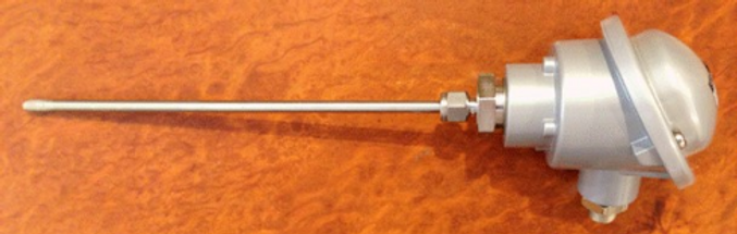
View of complete temperature probe
2. Installing temperature probes
Temperature probes can be installed at tapping points, with either same point or separate point fixing for the associated pressure probes. In both cases, the temperature probe (having a stem diameter of 6 mm) is inserted into a thermowell, 9.53 mm OD by 6.35 mm ID. The OD of the thermowell is the same size as the stem diameter of temperature probes commonly used for regular testing with portable instrumentation.

View of thermowell, with ½ inch process fitting (either BSPT or NPT), and separate instrumentation fitting to secure temperature probe in thermowell.
When the same tapping point is used for both the temperature and pressure probe, a slim-line custom tee-piece is first connected to the tapping point, with a ½ inch process fitting, and a longer thermowell passes through the tee-piece, and is screwed into the tee-piece. The pressure probe is then connected to the spare connection on the tee-piece via a ¼ inch gate or needle valve.
The temperature probes can readily be removed from the assembly for calibration checks or servicing, without disturbance to the system.
3. Checking calibration of the temperature probes
Each temperature probes is supplied with two temperature sensors, operating independently. Any significant discrepancy between the two sensors is detected by the MicroPM firmware, and an alert is provided to the operator, by HMI and/ or SCADA.
Calibration checks, or servicing, would only be necessary if the alert was permanent. To avoid nuisance warnings, the time period before an alert is set in firmware, to typically 1 minute.
When the pump is switched on or off, there may initially be quite high temperature transients, but after a few seconds these will settle down. The discriminator setting (adjustable in firmware) for alerting the user to differences between the two sensors is typically set to 1 or 2 mK, depending on pump head and application, when probes are operational.
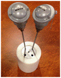
The long-term stability of the temperature measurements is typically better than 1 mK over 10 years, so alerts will be infrequent. If a fault occurs, and one of the sensors in a temperature probe reads significantly different from the other, a portable temperature indicator (see photo) can be used to identify which sensor is incorrect. Firmware then provides the option to temporarily continue with just the correctly reading sensor, until maintenance is available. Maintenance would consist of replacing both suction and discharge temperature probes with a spare set of matched probes. This procedure would take less than 30 minutes, including subsequent checks.
4. Design features to ensure correct temperature measurement
4.1 Dual temperature sensors with high sensitivity and long-term stability
Measurement of pump performance with heads down to 10 m of water. Automatic alert of any temperature calibration shift. Maintenance based on performance rather than time. Ability to switch to the back-up sensor until maintenance is available.
4.2 Early digitisation of transducer signals within the temperature probe handle
Benefits:
- Calibration stored internally, self-contained
- Calibration independent of external cables and differential inputs of remote circuity
- No significant signal interference from external electromagnetic fields
- Easy maintenance
- Probe identity stored on microprocessor
- In probe circuity to minimise sensor self-heating effects
4.3 Differential self-heating effect
Proprietary CoolTip™ technology reduces the differential self-heating effect to <0.02 mK, when temperature probes are in the fluid stream.
4.4 Differential stem effect
Stem effect is the heat inflow or outflow via the probe stem, where it is secured. The combination probe/ thermowell design minimises the differential effect when the immersion depth is > 50 mm.
4.5 Vibration heating and stress
The combination probe/ thermowell design minimises the free stem length. Longer stem lengths can cause vibration heating effects and mechanical stress issues, in particular at higher water velocities.
4.6 Viscous heating correction
The viscous heating effect is the name commonly used for the heating of temperature probes by the dissipation of the kinetic energy of the fluid. The measured (dynamic) temperature is the sum of the static temperature, under no flow conditions, plus an additional component due to kinetic energy effects, which is proportional to the square of the fluid velocity. The effect must be taken into account when pipe diameters are different at the suction and discharge measurement points. Correction is made in firmware.
5. Measurement accuracy
The main requirement for the thermodynamic method is the stable and accurate measurement of the differential temperature (dT), which will vary with total head and pump efficiency. Low head pumps give lower differential temperatures. Pumps with lower efficiencies give higher differential temperatures. The Robertson temperature probes measure dT to better than 1 mK. This allows measurements for pump heads down to about 10 m of water.
Table 1 shows dT as a function of pump efficiency and head, at a water temperature of 10 °C. The signal increases slightly with water temperature:

Table 1. dT (mK) at 10 °C (1 mK = 0.001°C)
Table 2 shows the effect on the pump efficiency measurement of an uncertainty in dT of 1 mK:

Table 2. % change in pump efficiency, for a 1mK variation in dT, at 10°C